Controlling an RGB LED with a 12LCD involves an Arduino microcontroller manages an RGB LED display and a 12-character LCD screen. Here’s a breakdown of the key components and steps involved in such a project:
Components Required:
- Arduino Board: The microcontroller used to control the LED and LCD.
- KY-016 RGB Full Color LED Module: An LED that can emit red, green, and blue light, which can be mixed to create a wide range of colors.
- 16×2 LCD Display with I2C Interface: A display screen that can show 12 characters at a time, used for showing messages or status updates.
- Breadboard and Jumper Wires: For creating the circuit connections.
- Power Supply: To power the Arduino and the components.
Steps to Control the RGB LED and 12LCD with Arduino:
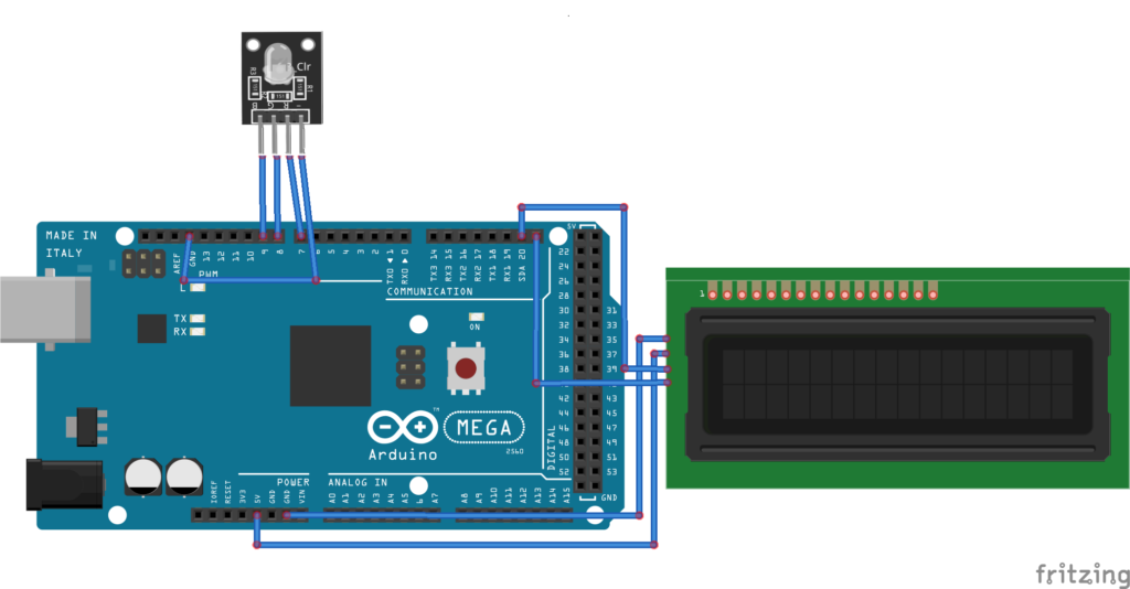
A. Circuit Setup:
- Connect the RGB LED to the Arduino with appropriate resistors on each color channel (red, green, blue).
- Connect the 12-character LCD to the Arduino. Typically, this involves connecting multiple pins for data lines, power, ground, and control signals. All the necessary setup items can be obtained here (RGB LED and 12LCD).
B. Programming the Arduino:
- Write an Arduino sketch (program) to control the RGB LED and the LCD.
- Use the
LiquidCrystallibrary to control the LCD. - Set up pins for the RGB LED and use PWM (Pulse Width Modulation) to control the color intensity.
- Display messages on the LCD and change the LED colors based on specific conditions or inputs.
C. Coding Logic:
- Initialize the LCD and set up the pin modes in the
setup()function. - In the
loop()function, write code to update the LCD display with the desired text. - Implement functions to change the RGB LED color by writing different PWM values to the red, green, and blue pins.
Example Code:
#include <Wire.h>
#include <LiquidCrystal_I2C.h>

// Initialize the library with the I2C address of the LCD (usually 0x27 or 0x3F)
LiquidCrystal_I2C lcd(0x27, 16, 2);

// RGB LED pins
const int redPin = 7;
const int greenPin = 8;
const int bluePin = 9;

// Function to set RGB LED color
void setColor(int red, int green, int blue) {
  analogWrite(redPin, red);
  analogWrite(greenPin, green);
  analogWrite(bluePin, blue);
}

void setup() {
  // Initialize the LCD
  lcd.init();
  lcd.backlight();  // Turn on the backlight

  // Set RGB LED pins as outputs
  pinMode(redPin, OUTPUT);
  pinMode(greenPin, OUTPUT);
  pinMode(bluePin, OUTPUT);

  // Initial message
  lcd.setCursor(0, 0);
  lcd.print("Color Cycle");
}

void loop() {
  // Define colors and corresponding messages
  struct Color {
    int red;
    int green;
    int blue;
    const char* name;
  } colors[] = {
    {255, 0, 0, "Red"},
    {0, 255, 0, "Green"},
    {0, 0, 255, "Blue"},
    {255, 255, 0, "Yellow"},
    {0, 255, 255, "Cyan"},
    {255, 0, 255, "Magenta"},
    {255, 255, 255, "White"},
    {0, 0, 0, "Off"}
  };

  // Loop through each color
  for (int i = 0; i < 8; i++) {
    // Set the color
    setColor(colors[i].red, colors[i].green, colors[i].blue);

    // Update the LCD with the color name
    lcd.clear();
    lcd.setCursor(0, 0);
    lcd.print("Current Color:");
    lcd.setCursor(0, 1);
    lcd.print(colors[i].name);

    // Wait for a second before changing to the next color
    delay(1000);
  }
}
Explanation:
- Libraries: The
Wire.handLiquidCrystal_I2C.hlibraries are included to handle I2C communication and control the LCD. - LCD Initialization: The
LiquidCrystal_I2Cobject is initialized with the I2C address of the LCD (usually 0x27 or 0x3F). - Pin Setup: The RGB LED pins are set as outputs.
- Color Array: An array of structures is used to store RGB values and corresponding color names.
- Main Loop:
- The program loops through each color in the array.
- The
setColorfunction is called to set the RGB LED to the specified color. - The LCD is cleared and updated with the color name.
- The program waits for one second before moving to the next color.
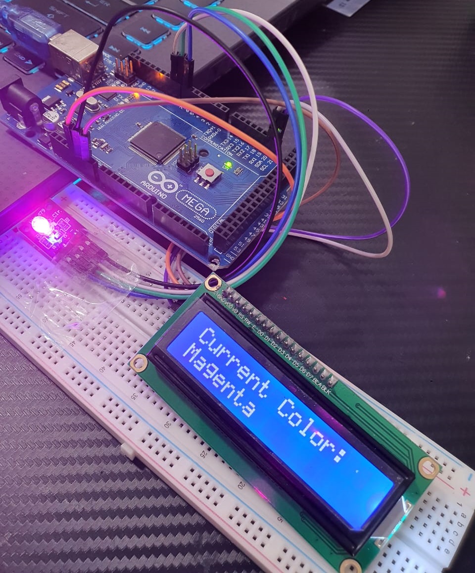
This setup and code will cycle through a predefined set of colors, displaying the name of the current color on the 16×2 I2C LCD while changing the RGB LED to match. Adjust the I2C address, pin numbers, and delay times as necessary to fit your specific hardware setup.
Expertise on Engineering.
Robotic and microcontroller are like toys to me.
I love playing with them.