A simple LED circuit with an Arduino Mega R3 refers to a basic circuit setup where an LED (Light Emitting Diode) is controlled by an Arduino Mega microcontroller. This is usually one of the first experiments that hobbyists and students do when they start learning about Arduino and electronics. The objective is to control the state of the LED (i.e., turning it ON and OFF) using the Arduino Mega R3. Here’s a simple guide on how to create a LED blinking circuit using the Arduino.
Materials Needed
- Arduino Mega 2560 R3 (or any other Arduino board)
- Breadboard
- 220 Ohm Resistor (Red – Red – Brown – Gold)
- LED (any color)
- Jumper wires
- USB cable to connect Arduino to computer
- Arduino Web Editor (online) or Arduino IDE software (offline)
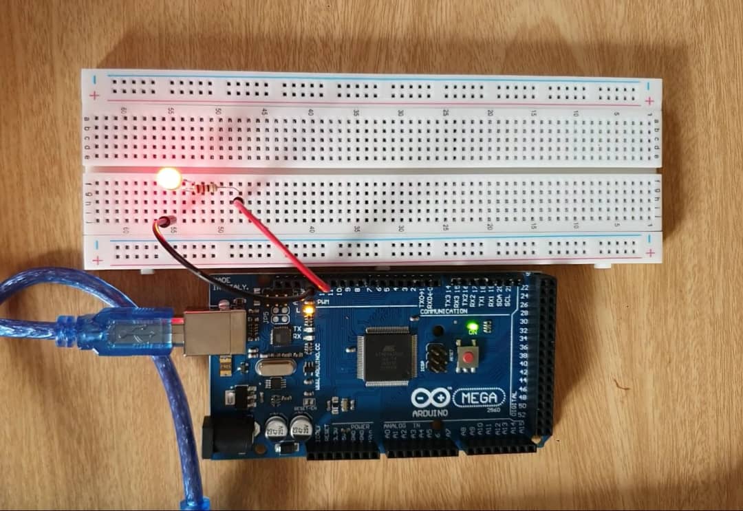
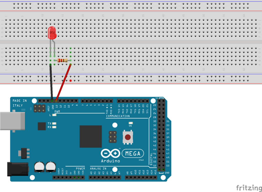
Simple Led Circuit with Arduino Mega R3 Circuit
Instructions
- Prepare your breadboard and components. Place your LED on your breadboard. Remember that the longer leg (anode) of the LED is the positive side and the shorter leg (cathode) is the negative side.
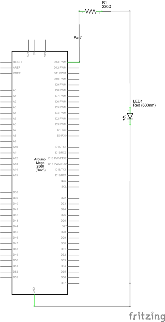
- Connect the LED to the Arduino. Connect one end of the 220-ohm resistor to the anode of the LED. Then connect the other end of the resistor to a digital pin on your Arduino Mega R3 for controlling the LED. For this tutorial, let’s use digital pin 13.
- Complete the circuit. Connect the cathode of the LED to one of the ground (GND) pins on your Arduino Mega R3.
- Write the Arduino Code. Open the Arduino IDE on your computer or Arduino Web IDE. You can use the example built-in Blink code in the Arduino Web IDE or others suitable code. This program will blink the LED on pin 13 on and off every second.
- Upload the Code. Connect your Arduino Mega R3 to your computer via a USB cable. In the Arduino IDE, select the correct board (Tools -> Board -> Arduino Mega or Mega 2560) and port (Tools -> Port). Then upload your code by clicking the “Upload” button.
- Test the Circuit. After uploading, the LED should blink on and off every second.
The LED on your breadboard should now blink on for one second, then off for one second, continuously. If your LED doesn’t blink as expected, double-check your wiring and your code. Make sure the LED is connected correctly (not backwards) and that the correct pin number is specified in the code.
Simple Led Circuit with Arduino Mega R3 Code
In other simple code, paste the following code:
// define LED pin
#define LED 13

void setup() {
  // set LED pin as output
  pinMode(LED, OUTPUT);
}

void loop() {
  // turn the LED on
  digitalWrite(LED, HIGH);
  delay(1000); // wait for a second
  // turn the LED off
  digitalWrite(LED, LOW);
  delay(1000); // wait for a second
}
Remember to always be careful when working with electrical components and double-check all of your connections before powering on your circuit. This Arduino has more I/O pins than the Uno, but the process of creating a simple LED circuit remains the same.
Expertise on Engineering.
Robotic and microcontroller are like toys to me.
I love playing with them.