Multiplexing operation in 4-digit 7-segment LED display is a technique used to drive multiple digits with a limited number of I/O pins by turning on one digit at a time in rapid succession. Here’s a detailed explanation of how this process works:
Components of a 4-Digit 7-Segment LED Display
- 7-Segment LEDs: Each digit is made up of seven segments (labeled a to g) and sometimes an additional segment for the decimal point (dp).
- Common Anode or Common Cathode: Each digit can have either a common anode or common cathode. In a common anode display, the anodes of all the segments in a digit are connected together, and in a common cathode display, the cathodes are connected together.
- Digit Select Lines: These are the control lines that select which digit is currently active.
How Multiplexing Works
The principle behind multiplexing is to light up one digit at a time but at a frequency high enough (typically around 60 Hz or higher) that human eyes perceive all digits as being lit simultaneously.
Steps Involved in Multiplexing:
- Time Division: The time period is divided into small intervals, each dedicated to one digit. For a 4-digit display, the time period is divided into four intervals.
- Digit Activation: Only one digit is activated at a time. For instance, in the first interval, the first digit is turned on, in the second interval, the second digit, and so on.
- Segment Data Update: During the interval when a particular digit is active, the segment lines are updated to display the correct segments for that digit.
- Cycle Repeat: This cycle repeats continuously. If done quickly enough, it creates the illusion that all digits are lit simultaneously.
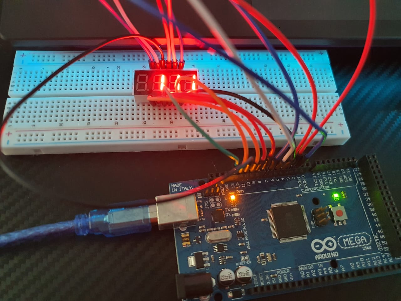
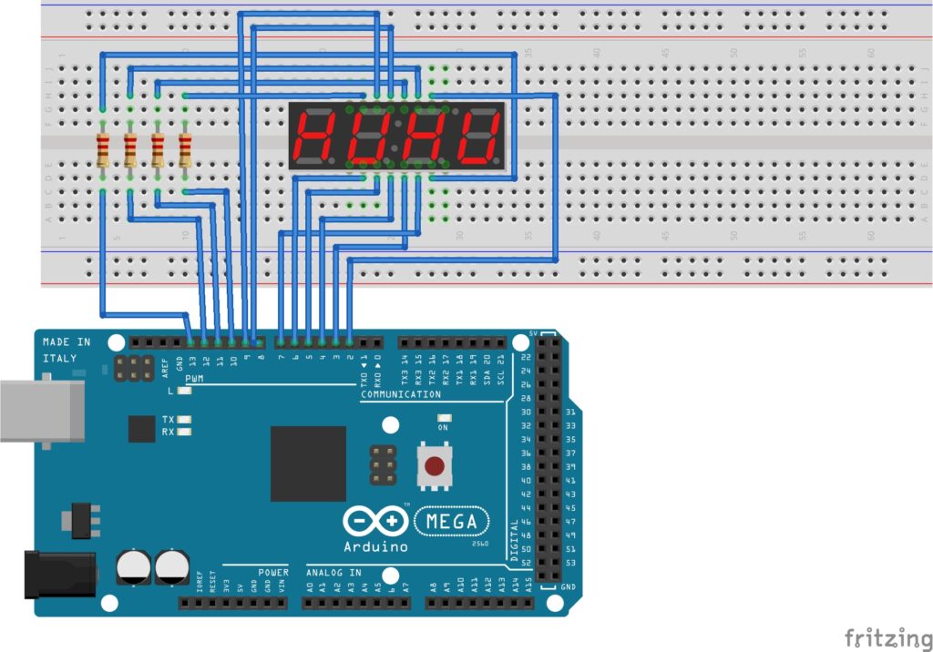
Multiplexing Implementation in 4-Digit 7-Segment LED Display with Arduino
Hardware Setup:
- Arduino Mega 2560 R3 (or any other Arduino board)
- Breadboard
- 4-digit 7-Segment Display (Common Anode or Common Cathode)
- Transistors/MOSFETs
- Current-Limiting Resistors
- Jumper wires
- USB cable to connect Arduino to computer
- Arduino Web Editor (online) or Arduino IDE software (offline)
Software Logic:
- Initialize: Set up the I/O pins for segment control and digit control.
- Digit Control Loop:
- Set the data for segments for the first digit.
- Enable the first digit by activating its control line.
- Wait for a short delay.
- Disable the first digit.
- Repeat the process for the second, third, and fourth digits.
Example Code Outline:
const int segmentPins[7] = {9, 2, 3, 5, 6, 8, 7}; // Pins connected to segments a-g
const int digitPins[4] = {10, 11, 12, 13}; // Pins connected to digits D1-D4

const byte digitCodes[10] = {
  // gfedcba (active low)
  0b11000000, // 0
  0b11111001, // 1
  0b10100100, // 2
  0b10110000, // 3
  0b10011001, // 4
  0b10010010, // 5
  0b10000010, // 6
  0b11111000, // 7
  0b10000000, // 8
  0b10010000  // 9
};

void setup() {
  for (int i = 0; i < 7; i++) {
    pinMode(segmentPins[i], OUTPUT);
  }
  for (int i = 0; i < 4; i++) {
    pinMode(digitPins[i], OUTPUT);
  }
}

void loop() {
  displayNumber(1111); // Example number to display
}

void displayNumber(int number) {
  int digits[4];
  for (int i = 3; i >= 0; i--) {
    digits[i] = number % 10;
    number /= 10;
  }

  for (int i = 0; i < 4; i++) {
    digitalWrite(digitPins[i], LOW);
    setSegments(digitCodes[digits[i]]);
    delay(500); // Small delay to stabilize the display
    digitalWrite(digitPins[i], HIGH);
  }
}

void setSegments(byte segments) {
  for (int i = 0; i < 7; i++) {
    digitalWrite(segmentPins[i], segments & (1 << i));
  }
}
Note: Ensure the loop runs fast enough to achieve the desired refresh rate. For example, if you want a refresh rate of 60 Hz per digit, the total refresh rate should be 240 Hz (since there are four digits).
Multiplexing operation in 4-digit 7-segment LED display involves rapidly switching between digits and updating their segment data, creating the appearance that all digits are lit continuously. This technique reduces the number of required I/O pins and is a common approach in microcontroller-based display systems.
Expertise on Engineering.
Robotic and microcontroller are like toys to me.
I love playing with them.