How does a 4-digit 7-segment LED display operate? A 4-digit 7-segment LED display operates by utilizing a combination of 7 individual LED segments arranged in a specific pattern to display numeric digits (0-9) and sometimes additional characters (such as letters or symbols). Each digit is composed of 7 segments arranged in a “figure-eight” pattern, with each segment capable of being independently turned on or off. By selectively activating the appropriate segments for each digit, the display can show numbers ranging from 0 to 9 on each of the four digits simultaneously, allowing for the display of various numerical values. Control circuits provide the necessary signals to activate the segments in the desired configuration to display the intended digits.
Here is a general overview of pinout of a 4-digit 7-segment LED display:
The pinout of a 4-digit 7-segment LED display comprises 12 pins. 8 of these pins correspond to the individual LEDs forming the segments, encompassing segments A through G and the decimal point (DP). The remaining four pins are allocated to represent each of the 4 digits, labeled D1 through D4.
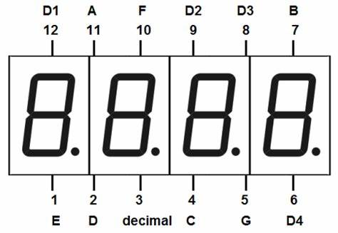
Four of these pins (D1, D2, D3, and D4) are used to control the individual digits and determine which signals pass through to the LED blocks. The remaining pins correspond to the individual segments.
- Common Anode 4-Digit 7-Segment Display:
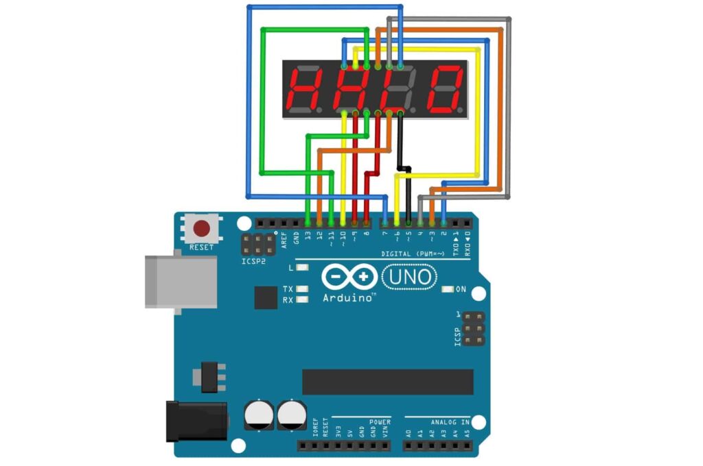
To turn on a digit on a common anode LED display, we need to set the corresponding pin to HIGH. Conversely, to turn it off, we need to set the pin to LOW. Additionally, the ON/OFF state of the segments corresponds to the LOW/HIGH signals from the Arduino.
byte D1 = 2;
byte D2 = 3;
byte D3 = 4;
byte D4 = 5;
byte A = 6;
byte B = 7;
byte C = 8;
byte D = 9;
byte E = 10;
byte F = 11;
byte G = 12;
byte DP = 13; // decimal point
// Define the input pins for the 7-segment display segments.
const int segmentPins[] = {A, B, C, D, E, F, G, DP};
// Define the input pins for the 7-segment display digits.
const int digitPins[] = {D1, D2, D3, D4};
// For common anode coding:
uint8_t digitON = HIGH;
uint8_t digitOFF = LOW;
uint8_t segmentON = LOW;
uint8_t segmentOFF = HIGH;
void setup() {
// Pin initialization.
for (int i = 0; i < 8; i++) {
pinMode(segmentPins[i], OUTPUT);
}
for (int i = 0; i < 4; i++) {
pinMode(digitPins[i], OUTPUT);
digitalWrite(digitPins[i], digitOFF);
}
}
void loop() {
digitalWrite(D1, digitON); // Turn on the first digit
digitalWrite(D2, digitON);
digitalWrite(D3, digitON);
digitalWrite(D4, digitON);
digitalWrite(A, segmentON);
digitalWrite(B, segmentON);
digitalWrite(C, segmentON);
digitalWrite(D, segmentON);
digitalWrite(E, segmentON);
digitalWrite(F, segmentON);
digitalWrite(G, segmentON);
digitalWrite(DP, segmentON);
}
2. Common Cathode 4-Digit 7-Segment Display:
To turn on a digit on a common cathode LED display, we need to set the corresponding pin to LOW. Meanwhile, to turn it off, we need to set the pin to HIGH. Furthermore, the ON/OFF state of the segments corresponds to the HIGH/LOW signals from the Arduino.
byte D1 = 2;
byte D2 = 3;
byte D3 = 4;
byte D4 = 5;
byte A = 6;
byte B = 7;
byte C = 8;
byte D = 9;
byte E = 10;
byte F = 11;
byte G = 12;
byte DP = 13; // decimal point
// Define the input pins for the 7-segment display segments.
const int segmentPins[] = {A, B, C, D, E, F, G, DP};
// Define the input pins for the 7-segment display digits.
const int digitPins[] = {D1, D2, D3, D4};
// For common Cathode coding:
uint8_t digitON = LOW;
uint8_t digitOFF = HIGH;
uint8_t segmentON = HIGH;
uint8_t segmentOFF = LOW;
void setup() {
// Pin initialization.
for (int i = 0; i < 8; i++) {
pinMode(segmentPins[i], OUTPUT);
}
for (int i = 0; i < 4; i++) {
pinMode(digitPins[i], OUTPUT);
digitalWrite(digitPins[i], digitOFF);
}
}
void loop() {
digitalWrite(D1, digitOFF); // Turn on the first digit
digitalWrite(D2, digitOFF);
digitalWrite(D3, digitOFF);
digitalWrite(D4, digitOFF);
digitalWrite(A, segmentOFF);
digitalWrite(B, segmentOFF);
digitalWrite(C, segmentOFF);
digitalWrite(D, segmentOFF);
digitalWrite(E, segmentOFF);
digitalWrite(F, segmentOFF);
digitalWrite(G, segmentOFF);
digitalWrite(DP, segmentOFF);
}
Below is the step of a 4-digit 7-segment display:
The 4-digit 7-segment display involves several steps to display desired numbers or characters:
- Multiplexing: In multiplexing, each digit of the display is activated sequentially for a brief period. This process occurs rapidly, giving the illusion that all digits are active simultaneously. By cycling through each digit quickly, the display can show multiple numbers or characters.
- Segment Activation: For each digit, the appropriate segments corresponding to the desired number or character are activated. For example, to display the numeral “0”, segments A, B, C, D, E, F are illuminated while segment G remains off. The combination of illuminated segments forms the shape of the desired numeral or character.
- Digit Selection: While the segments are activated for each digit, the specific digit to be displayed is selected. This is achieved by applying a voltage or grounding to the common pin associated with that digit.
- Repeat: The process repeats for each digit in sequence, cycling through all digits rapidly to create the illusion of a complete display showing multiple numbers or characters.
Overall, by multiplexing the display and selectively activating segments for each digit, the 4-digit 7-segment display can effectively present a variety of numbers, letters, or symbols, providing information in a clear and concise manner.
Let’s take a look into its common application:
4-digit 7-segment displays are widely used across various industries and sectors due to their versatility and ease of use. Here are some common applications:
- Digital Clocks and Timers: 4-digit 7-segment displays are widely used in digital clocks, timers, and countdown devices to display time in hours, minutes, and seconds.
- Counters and Scoreboards: They are used in electronic counters and scoreboards to display numerical values, such as the count of products in manufacturing lines or the score in sports events.
- Measurement Instruments: 4-digit 7-segment displays are employed in measurement instruments like multimeters, voltmeters, ammeters, and frequency counters to display readings and measurements.
- Temperature Displays: They are utilized in thermostats, temperature controllers, and weather stations to display temperature readings in degrees Celsius or Fahrenheit.
- Consumer Electronics: These displays can be found in various consumer electronic devices such as digital watches, alarm clocks, microwave ovens, and kitchen timers.
- Instrument Panels: In automotive and industrial settings, 4-digit 7-segment displays are used in instrument panels to display various parameters like speed, RPM, fuel level, and engine temperature.
- Information Displays: They are used in information displays at railway stations, airports, and public places to show departure and arrival times, gate numbers, and other relevant information.
- Digital Signage: 4-digit 7-segment displays are used in digital signage systems for advertising, displaying prices in retail stores, and conveying information in public spaces.
- Educational Projects: They are commonly used in educational projects and hobbyist electronics to teach basic digital electronics concepts and build simple electronic circuits.
- Industrial Automation: In industrial automation systems, these displays are used for process monitoring, displaying machine status, and conveying important information to operators.
Overall, 4-digit 7-segment displays are versatile components with a wide range of applications in both commercial and industrial settings, as well as in educational and hobbyist projects.
While 7-segment displays are versatile and widely used, they do have some limitations:
Indeed, while 4-digit 7-segment displays offer versatility and widespread application, they come with several limitations:
- Limited Display Options: These displays primarily show numeric characters (0-9) and a few symbols like decimal points. They lack the capability to display alphabetic characters or complex graphical information.
- Low Resolution: Each digit consists of seven segments, restricting the display’s ability to render detailed graphics or text compared to higher-resolution displays.
- Monochromatic Output: Typically, these displays emit light in a single color (e.g., red, green, blue), lacking the ability to display multiple colors simultaneously like RGB LED displays.
- Limited Brightness Control: While brightness can be adjusted to some extent, precise control over brightness levels may be challenging compared to other display technologies.
- Viewing Angle Dependence: Visibility can diminish at extreme viewing angles or in bright ambient lighting conditions, affecting the display’s readability.
- Space Requirements: Applications requiring multiple digits may demand considerable physical space, especially when accommodating larger displays or complex arrangements.
- Power Consumption: Depending on size and brightness, 4-digit 7-segment displays can consume significant power, especially when all digits are active simultaneously.
- Environmental Sensitivity: Traditional displays may lack robustness against environmental factors such as moisture, dust, and temperature variations, impacting longevity and reliability.
Despite these limitations, 4-digit 7-segment displays remain popular due to their simplicity, cost-effectiveness, and ease of integration into various electronic systems. In the next article, we’ll explore on how 4-digit 7-segment LED display operates with an Arduino, including various operations.
Expertise on Engineering.
Robotic and microcontroller are like toys to me.
I love playing with them.