7 Segment Display with Arduino Mega. 7 Segment Display is one of electronic device, uses to display numerical digits from 0 to 9, as well as some alphanumeric characters and symbols. It is an alternative to the more complex dot matrix displays. In this article, basic circuit and coding using Arduino MEGA 2560 R3 is presented to provide comprehension prior to embarking on a larger project.
Fundamental
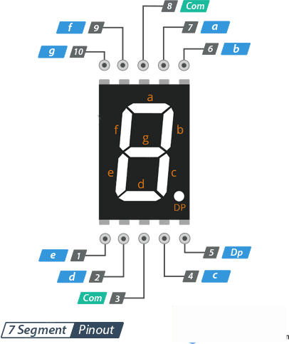
A 7-segment display character refers to any digit (0-9) or certain alphanumeric characters and symbols that can be displayed using a 7-segment display. Each character is composed of seven individually controllable segments arranged in a specific pattern, allowing for the representation of different numbers and characters.
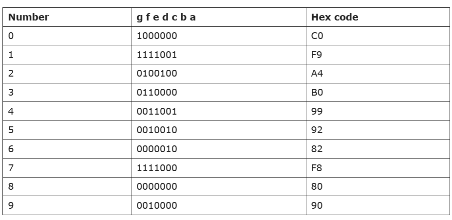
The Table below displays the codes for digits 0 through 9 on the 7-segment display.
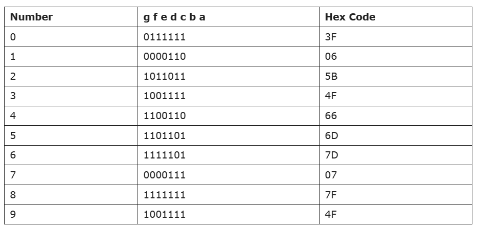
The scenario shifts when considering a common cathode configuration.
Materials Needed
- Arduino Mega 2560 R3 (or any other Arduino board)
- Breadboard
- 7 Segment Display
- 8 pcs Resistor 220 Ohm
- Jumper wires
- USB cable to connect Arduino to computer
- Arduino Web Editor (online) or Arduino IDE software (offline)
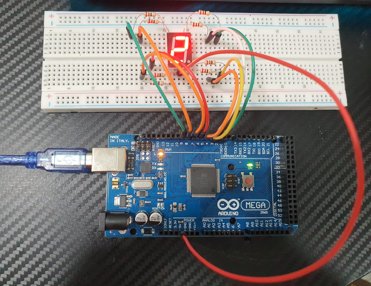
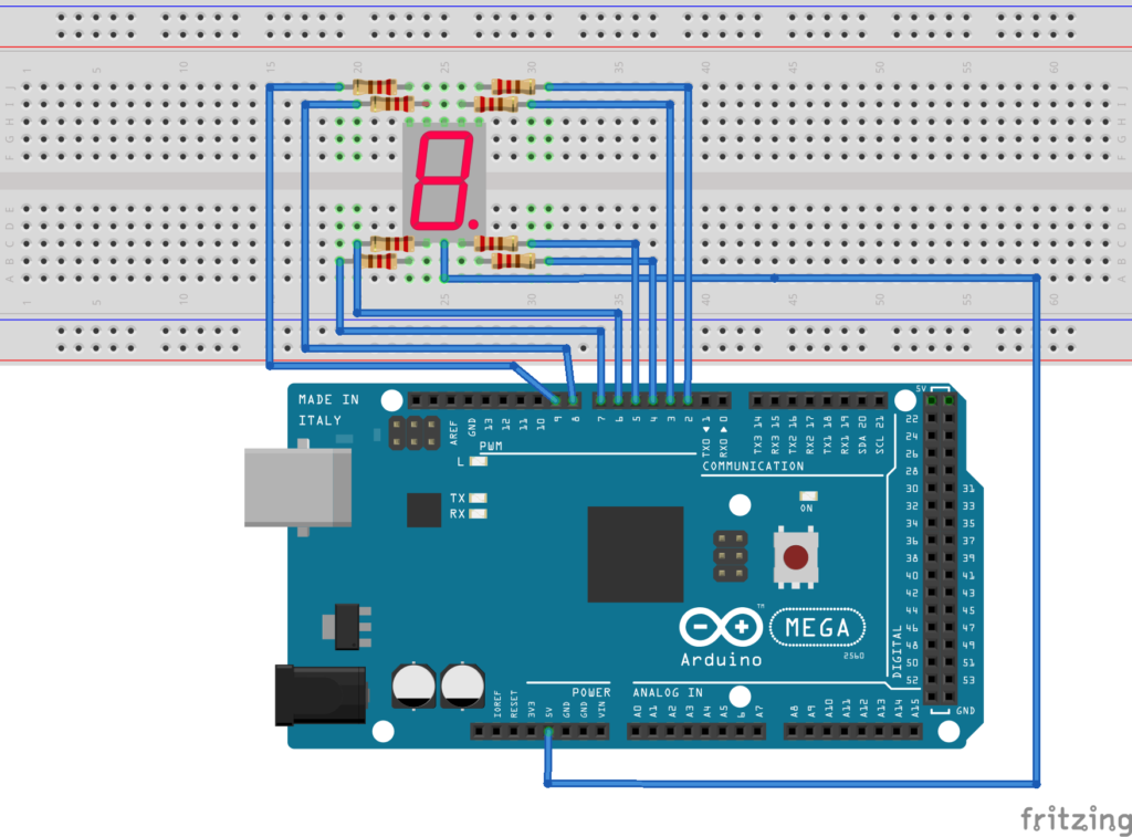
7 Segment Display Circuit (Common Anode)
7 Segment Display Code (Common Anode)
In other simple code, paste the following code:
include <SevSeg.h>
SevSeg sevseg;
void setup()
{
byte numDigits = 1;
byte digitPins[] = {};
byte segmentPins[] = {3, 2, 5, 6, 7, 8, 9, 4};
bool resistorsOnSegments = true;
byte hardwareConfig = COMMON_ANODE;
sevseg.begin(hardwareConfig, numDigits, digitPins, segmentPins, resistorsOnSegments);
sevseg.setBrightness(90);
}
void loop()
{
sevseg.setNumber(2);
sevseg.refreshDisplay();
}
*If you’re using the cathode configuration, you can replace the code with the following line: byte hardwareConfig = COMMON_CATHODE; and make sure the wiring connection is in cathode configuration.
Note: make sure you include the SevSeg.h zip file in your Arduino library.
7 Segment Display Code; Countdown / Timer in Ascending Order (Common Anode)
include <SevSeg.h>
SevSeg sevseg;
void setup(){
byte numDigits = 1;
byte digitPins[] = {};
byte segmentPins[] = {3, 2, 5, 6, 7, 8, 9, 10};
bool resistorsOnSegments = true;
byte hardwareConfig = COMMON_ANODE;
sevseg.begin(hardwareConfig, numDigits, digitPins, segmentPins, resistorsOnSegments);
sevseg.setBrightness(90);
}
void loop()
{
for(int i = 0; i < 10; i++)
{
sevseg.setNumber(i, i%2);
delay(1000);
sevseg.refreshDisplay();
}
}
*If you’re using the cathode configuration, you can replace the code with the following line: byte hardwareConfig = COMMON_CATHODE; and make sure the wiring connection is in cathode configuration. Furthermore, If you’re using the decending order, you can replace the code with the following line: for ( int i = 9; i > 0; i–);
Note: makesure you include the SevSeg.h zip file in your Arduino library.
This project appears to be relatively straightforward, doesn’t it? Therefore, you could enhance it by integrating additional components such as a push button and traffic light module. By examining the relationship between push buttons and traffic light module within this framework, you could broaden the scope of this project into something more substantial.
Expertise on Engineering.
Robotic and microcontroller are like toys to me.
I love playing with them.