
LED Blinking with a Push Button using Fritzing refers to creating a visual circuit diagram using Fritzing software to illustrate how to connect and wire the components for an LED blinking project with a push button.
Fritzing is a popular open-source software tool that allows users to create electronic schematics, PCB layouts, and breadboard views. It provides an intuitive interface for designing circuits and documenting projects.
To create a Fritzing diagram for LED blinking with a push button, you would typically use the Fritzing software to drag and drop the components onto a virtual breadboard, and then connect them accordingly.
To build an LED blinking project with a push button, you will need the following materials:
- Light Emitting Diode, LED (any colour)
- Push button switch
- Resistor (220-470 ohms)
- Breadboard or a prototyping board
- Jumper wires
- Power supply (Battery 4.8V)
The general steps to create a Fritzing diagram for LED blinking with a push button are as follows:
- Open Fritzing and create a new project.
- Choose the required components from the Fritzing parts library, including LED, push button, resistor, and breadboard.
- Drag and drop a breadboard onto the workspace.
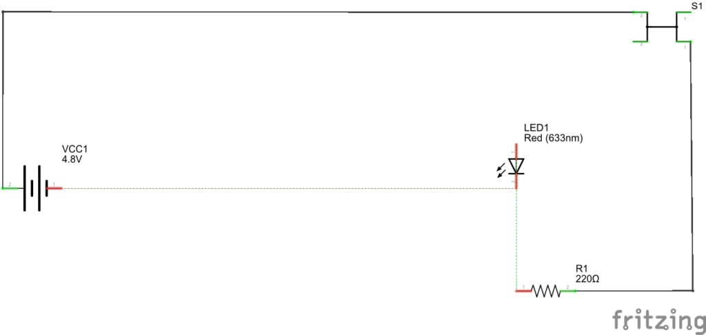
- Place the LED on the breadboard, making sure to connect the anode (longer leg) to a current-limiting resistor.
- Connect the cathode (shorter leg) of the LED to a negative terminal (anode) of power supply.
- Place the push button on the breadboard, ensuring its legs span the center trench.
- Connect one leg of the push button to the to a current-limiting resistor.
- Connect the other leg of the push button to a positive terminal (cathode) of power supply.
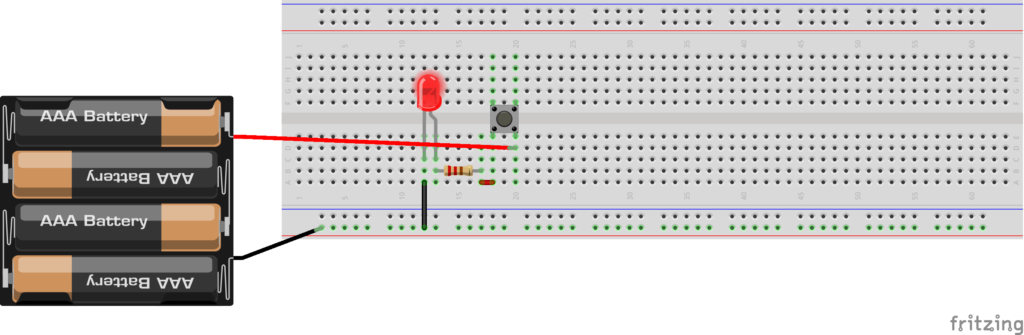
Wire up your materials as shown in breadboad diagram below. Once you have it wired up, try pressing the button by changing the switch status into pressed or released in the inspector section.
That is it! You have now successfully created the circuit for LED blinking with a push button. Remember, Fritzing diagrams are visual representations of circuits, so it’s important to ensure accuracy, clarity, and proper documentation. Let me know if you have any further questions. Next article we will create an LED blinking project with a push button using Arduino.
Expertise on Engineering.
Robotic and microcontroller are like toys to me.
I love playing with them.