
A common anode LED dot matrix display, such as the 1088BS, has all the anodes (positive terminals) of the LEDs in each row connected together, and all the cathodes (negative terminals) connected in columns. This configuration means you control the individual LEDs by grounding the appropriate column (cathode) and providing power to the appropriate row (anode).
Understanding Common Anode Configuration
In a common anode configuration:
- Rows are connected to the positive voltage (anode).
- Columns are connected to ground (cathode) to light up the individual LEDs.
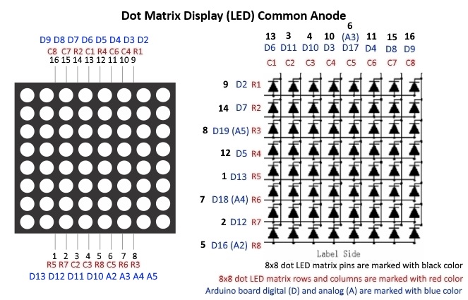
Pin Configuration
Here’s the typical pin configuration for a common anode 8×8 LED dot matrix display like the 1088BS:
Driving the Display
To drive a common anode LED matrix, you need to set the row pins high (to supply power) and set the column pins low (to ground the cathode of the LED you want to light up). This is usually done through multiplexing to control each LED individually without requiring a large number of GPIO pins.
Example with Arduino
Here’s an example code for controlling a common anode 8×8 LED matrix with an Arduino:
const int row[8] = {2, 3, 4, 5, 6, 7, 8, 9}; // Row pins
const int col[8] = {10, 11, 12, 13, A0, A1, A2, A3}; // Column pins

byte smiley[8] = {
  B00111100,
  B01000010,
  B10100101,
  B10000001,
  B10100101,
  B10011001,
  B01000010,
  B00111100
};

void setup() {
  for (int i = 0; i < 8; i++) {
    pinMode(row[i], OUTPUT);
    pinMode(col[i], OUTPUT);
    digitalWrite(col[i], HIGH); // Turn off all columns (by default)
  }
}

void loop() {
  for (int i = 0; i < 8; i++) {
    digitalWrite(row[i], HIGH); // Activate row
    for (int j = 0; j < 8; j++) {
      digitalWrite(col[j], !(smiley[i] & (1 << j))); // Light up the appropriate LEDs
    }
    delay(2); // Small delay for multiplexing
    digitalWrite(row[i], LOW); // Deactivate row
  }
}
Explanation of the Code
- Pin Initialization: The
setupfunction initializes the row and column pins as outputs and sets all columns high (turning off all LEDs initially). - Main Loop: The
loopfunction iterates through each row. For each row, it:
- Activates the current row by setting the corresponding pin high.
- Iterates through each column, setting the column pin low if the corresponding bit in the
smileyarray is 1 (turning on the LED). - Introduces a small delay to ensure the LED is visible (multiplexing delay).
- Deactivates the row by setting the pin low.
Multiplexing
Multiplexing is crucial because it allows you to control all 64 LEDs using only 16 pins (8 for rows and 8 for columns) by lighting up one row (or column) at a time very quickly, faster than the human eye can detect. This method ensures efficient use of microcontroller pins and reduces the complexity of wiring and control logic.
Expertise on Engineering.
Robotic and microcontroller are like toys to me.
I love playing with them.