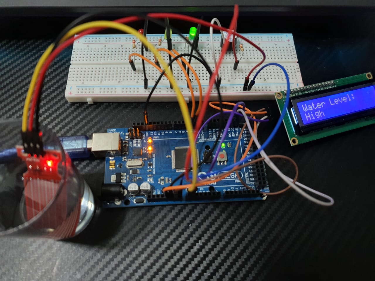
To create a water level indicator using LCD display and the HW-038 Water Level Sensor Module, you may combine with other components such as LEDs and Active Buzzer Tone Piezo and write the corresponding Arduino code. Here’s a step-by-step guide to help you build this project.
Components Needed:
- HW-038 Water Level Sensor Module
- Active Buzzer Tone Piezo
- LCD Display (16×2) with I2C module (HW-061)
- LEDs (Green, Yellow, Red)
- Resistors (220 ohms for LEDs)
- Resistor (150 ohms for LEDs)
- Arduino
- Connecting wires
- Breadboard or PCB for assembly
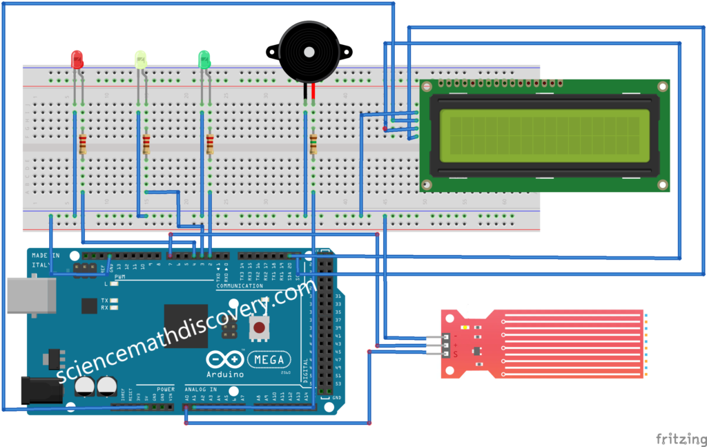
Circuit Diagram:
Steps:
A. Connect the HW-038 Water Level Sensor:
- Connect the VCC pin of the HW-038 to the 5V pin on the Arduino.
- Connect the GND pin of the HW-038 to the GND pin on the Arduino.
- Connect the AO (Analog Output) pin of the HW-038 to an analog input pin on the Arduino (e.g., A0).
B. Connect the LEDs:
- Connect the anode (long leg) of the Green LED to a 220-ohm resistor and then to digital pin 2 on the Arduino. Connect the cathode (short leg) to GND.
- Connect the anode of the Yellow LED to a 220-ohm resistor and then to digital pin 3 on the Arduino. Connect the cathode to GND.
- Connect the anode of the Red LED to a 220-ohm resistor and then to digital pin 4 on the Arduino. Connect the cathode to GND.
C. Connect the Active Piezo Buzzer:
- Connect the positive terminal of the buzzer to a 150-ohm resistor and then to digital pin A1 on the Arduino.
- Connect the negative terminal of the buzzer to GND.
D. Connect the LCD Display:
- Connect the SDA and SCL pins of the LCD display to the corresponding SDA and SCL pins on the Arduino (A2 for SDA and A3 for SCL on an Arduino Uno).
- Connect the VCC pin of the LCD to the 5V pin on the Arduino.
- Connect the GND pin of the LCD to the GND pin on the Arduino.
Arduino Code:
#include <Wire.h>
#include <LiquidCrystal_I2C.h>
/* Change these values based on your calibration values */
int lowerThreshold = 100;
int mediumThreshold = 250;
int upperThreshold = 500;
// Sensor pins
#define sensorPower 7
#define sensorPin A0
#define buzzerPin A1
// Declare pins to which LEDs are connected
int redLED = 4;
int yellowLED = 3;
int greenLED = 2;
// Value for storing water level
int val = 0;
// Initialize the LCD
LiquidCrystal_I2C lcd(0x27, 16, 2); // Set the LCD address to 0x27 for a 16 chars and 2 line display
void setup() {
pinMode(sensorPin, INPUT);
pinMode(buzzerPin, OUTPUT);
// Set LED pins as an OUTPUT
pinMode(redLED, OUTPUT);
pinMode(yellowLED, OUTPUT);
pinMode(greenLED, OUTPUT);
// Initially turn off all LEDs
digitalWrite(redLED, LOW);
digitalWrite(yellowLED, LOW);
digitalWrite(greenLED, LOW);
lcd.init(); // Initialize the LCD
lcd.backlight(); // Turn on the backlight
Serial.begin(9600); // Initialize serial communication for debugging
}
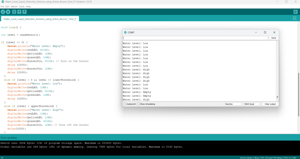
void loop() {
// Read the analog value from the sensor
int level = readSensor();
if (level == 0) {
Serial.println("Water Level: Empty");
// Display the water level on the LCD
lcd.clear();
lcd.setCursor(0, 0);
lcd.print("Water Level:");
lcd.setCursor(0, 1);
lcd.print("Empty");
digitalWrite(redLED, HIGH);
digitalWrite(yellowLED, LOW);
digitalWrite(greenLED, LOW);
digitalWrite(buzzerPin, HIGH); // Turn on the buzzer
delay (1000);
digitalWrite(buzzerPin, LOW);
delay (1000);
}
else if (level > 0 && level <= lowerThreshold) {
Serial.println("Water Level: Low");
// Display the water level on the LCD
lcd.clear();
lcd.setCursor(0, 0);
lcd.print("Water Level:");
lcd.setCursor(0, 1);
lcd.print("Low");
digitalWrite(redLED, LOW);
digitalWrite(yellowLED, HIGH);
digitalWrite(greenLED, LOW);
delay (1000);
}
else if (level > upperThreshold) {
Serial.println("Water Level: High");
// Display the water level on the LCD
lcd.clear();
lcd.setCursor(0, 0);
lcd.print("Water Level:");
lcd.setCursor(0, 1);
lcd.print("High");
digitalWrite(redLED, LOW);
digitalWrite(yellowLED, LOW);
digitalWrite(greenLED, HIGH);
digitalWrite(buzzerPin, LOW); // Turn off the buzzer
delay(1000);
}
}
//This is a function used to get the reading
int readSensor() {
digitalWrite(sensorPower, HIGH);
delay(10);
val = analogRead(sensorPin);
digitalWrite(sensorPower, LOW);
return val;
}Explanation:
LCD Initialization:
- The
LiquidCrystal_I2Clibrary is used to control the LCD display with I2C communication. - The LCD address is set to
0x27, which is common for many I2C LCD modules. Adjust if your module has a different address.
Main Loop:
- The code reads the sensor value from the HW-038.
- The water level is displayed on the LCD.
- LEDs are controlled based on the water level:
- Green LED indicates a HIGH water level.
- Yellow LED indicates a LOW water level.
- Red LED indicates a EMPTY water level.
- If the water level EMPTY, the buzzer is activated for 1 seconds.
Serial Monitor:
- The analog value from the sensor is printed to the Serial Monitor for debugging and calibration.
A water level indicator using an LCD display provides a visual representation of the water level in a tank or reservoir. Here’s a summary of the project:
Objective:
The objective of the project is to design a system that can accurately measure the water level and display it in a user-friendly manner using an LCD display.
Components Needed:
- HW-061 Water Level Sensor Module
- 16×2 LCD Display with I2C module
- Arduino Mega
- Connecting wires
- Breadboard or PCB for assembly
Implementation Steps:
- Hardware Setup:
- Connect the HW-061 water level sensor to the Arduino Mega to measure the water level.
- Connect the 16×2 LCD display with an I2C module to the Arduino Mega for visual output.
- Software Setup:
- Install the LiquidCrystal_I2C library in the Arduino IDE for controlling the LCD display.
- Write the Arduino code to read sensor data and display the water level on the LCD.
- Coding:
- Use analogRead() to read the sensor value from the HW-061 sensor.
- Use conditional logic to determine the water level based on sensor readings.
- Display the water level messages (“Empty”, “Low”, “Medium”, “High”) on the LCD using the LiquidCrystal_I2C library.
- Testing and Calibration:
- Upload the code to the Arduino Mega and test the system.
- Calibrate the sensor thresholds if necessary to ensure accurate readings.
Conclusion:
A water level indicator using an LCD display provides a simple and effective way to monitor water levels in tanks or reservoirs. By displaying intuitive messages on the LCD, users can quickly understand the current water level status. This project demonstrates the use of Arduino and basic electronics components to create a practical solution for water level monitoring.
Expertise on Engineering.
Robotic and microcontroller are like toys to me.
I love playing with them.