Creating a water level indicator using HW-038 sensor with LEDs is a straightforward project. The HW-038 sensor is an inexpensive module that detects the presence of water and outputs a digital signal. Here’s a simple circuit and code to get you started:
Components Needed:
- HW-038 water level sensor
- LEDs (any color)
- Resistors (220 ohms)
- Arduino board (e.g., Arduino Uno)
- Breadboard and jumper wires
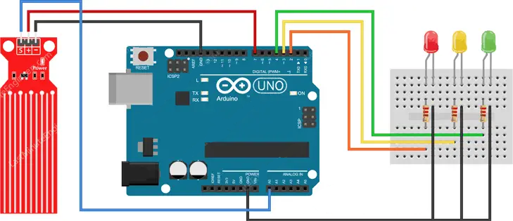
Water Level Indicator Circuit Diagram:

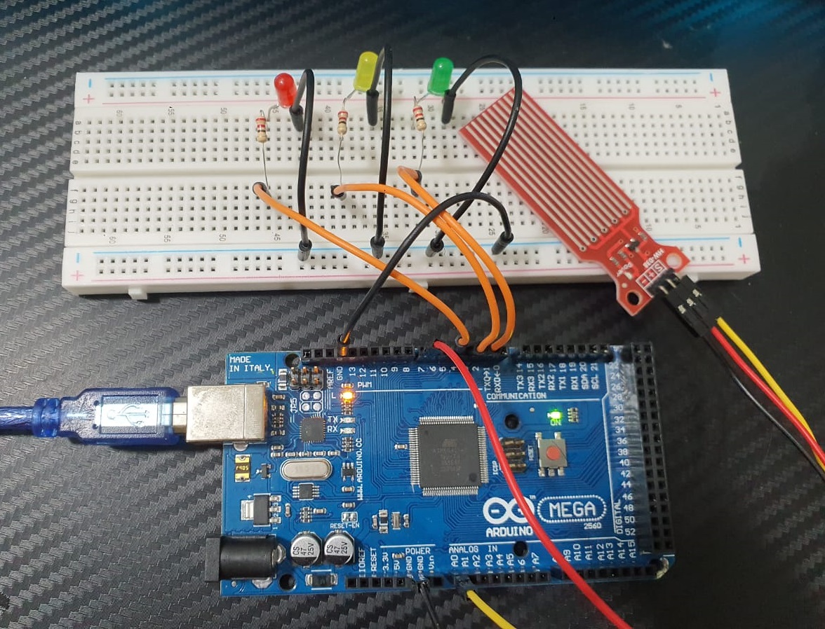
Connect the components as follows:
- Connect the VCC pin of the HW-038 sensor to the 5V pin of the Arduino.
- Connect the GND pin of the HW-038 sensor to the GND pin of the Arduino.
- Connect the OUT pin of the HW-038 sensor to a digital pin (e.g., pin 2) of the Arduino.
- Connect each LED to a digital pin through a 220ohm resistor (one end of the resistor to the pin, the other end to the LED anode). Connect the cathodes of all LEDs to GND.
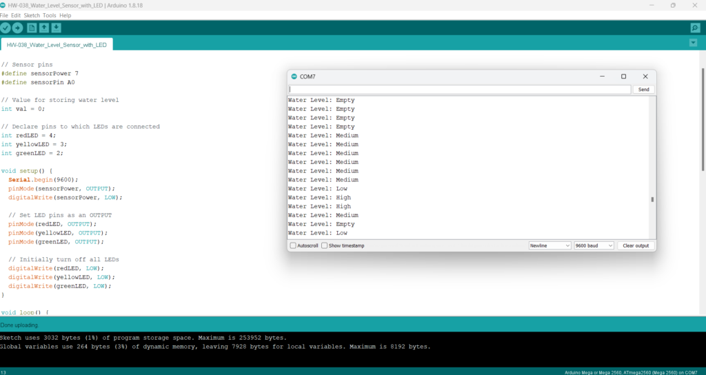
Water Level Indicator using HW-038 Sensor with LEDs Coding:
/* Change these values based on your calibration values */
int lowerThreshold = 420;
int upperThreshold = 520;

// Sensor pins
#define sensorPower 7
#define sensorPin A0

// Value for storing water level
int val = 0;

// Declare pins to which LEDs are connected
int redLED = 4;
int yellowLED = 3;
int greenLED = 2;

void setup() {
  Serial.begin(9600);
  pinMode(sensorPower, OUTPUT);
  digitalWrite(sensorPower, LOW);

  // Set LED pins as an OUTPUT
  pinMode(redLED, OUTPUT);
  pinMode(yellowLED, OUTPUT);
  pinMode(greenLED, OUTPUT);

  // Initially turn off all LEDs
  digitalWrite(redLED, LOW);
  digitalWrite(yellowLED, LOW);
  digitalWrite(greenLED, LOW);
}

void loop() {
  int level = readSensor();

  if (level == 0) {
    Serial.println("Water Level: Empty");
    digitalWrite(redLED, LOW);
    digitalWrite(yellowLED, LOW);
    digitalWrite(greenLED, LOW);
  }
  else if (level > 0 && level <= lowerThreshold) {
    Serial.println("Water Level: Low");
    digitalWrite(redLED, HIGH);
    digitalWrite(yellowLED, LOW);
    digitalWrite(greenLED, LOW);
  }
  else if (level > lowerThreshold && level <= upperThreshold) {
    Serial.println("Water Level: Medium");
    digitalWrite(redLED, LOW);
    digitalWrite(yellowLED, HIGH);
    digitalWrite(greenLED, LOW);
  }
  else if (level > upperThreshold) {
    Serial.println("Water Level: High");
    digitalWrite(redLED, LOW);
    digitalWrite(yellowLED, LOW);
    digitalWrite(greenLED, HIGH);
  }
  delay(1000);
}

//This is a function used to get the reading
int readSensor() {
  digitalWrite(sensorPower, HIGH);
  delay(10);
  val = analogRead(sensorPin);
  digitalWrite(sensorPower, LOW);
  return val;
}
How It Works:
- The HW-038 sensor outputs a digital HIGH signal when it detects water and LOW when there’s no water.
- In the Arduino code, we read the state of the sensor pin.
- If water is detected, all LEDs will turn on; otherwise, they will remain off.
- The
delay(1000)function ensures that the sensor is not read too frequently, preventing rapid changes in LED states due to sensor noise.

Make sure to calibrate the HW-038 sensor according to your needs, especially regarding the sensitivity level. You can add more LEDs to indicate different water levels or use a single multicolor LED for visual feedback. Adjust the code accordingly to control them. Always double-check your connections and ensure that the circuit is properly powered.
Expertise on Engineering.
Robotic and microcontroller are like toys to me.
I love playing with them.
