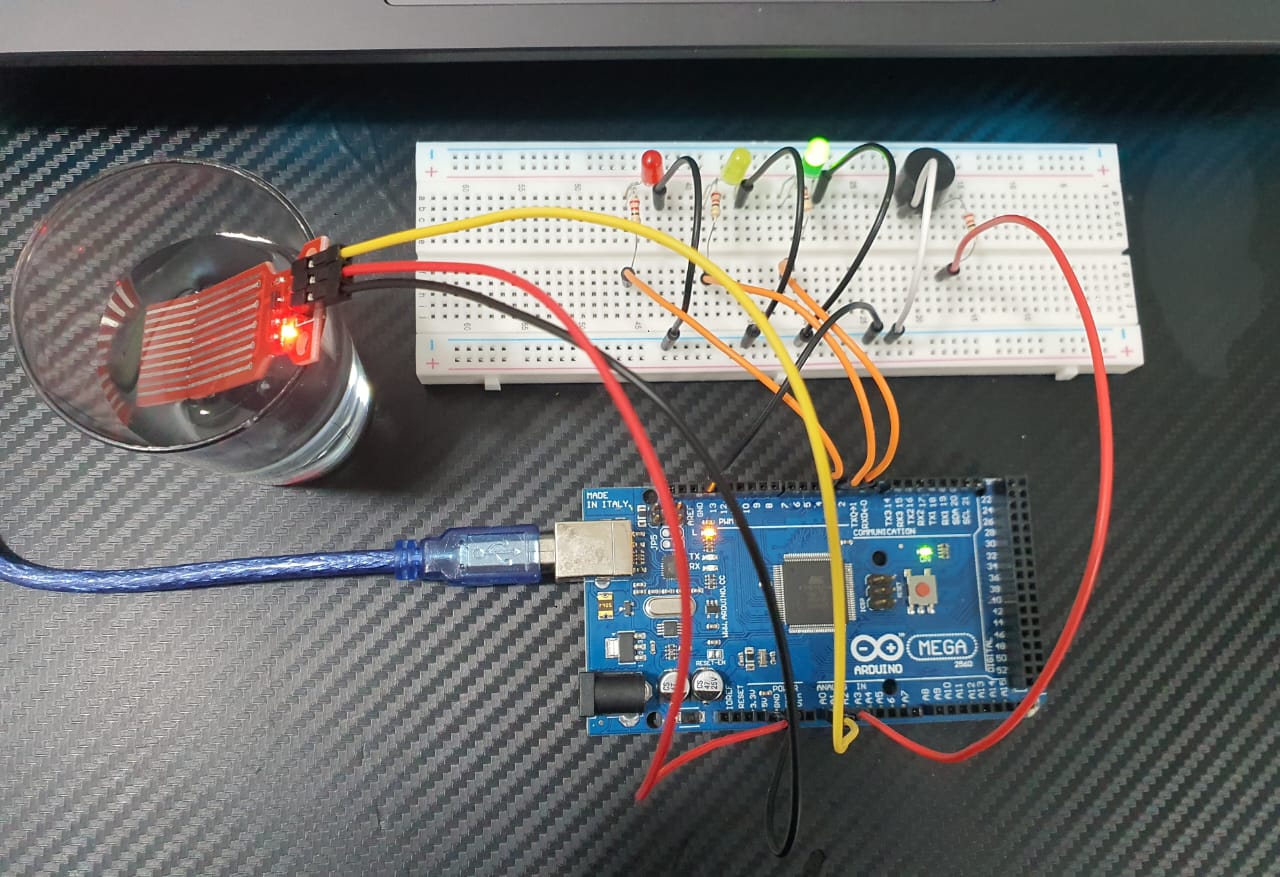
Creating a water level indicator using an active piezo buzzer for tone indication is a practical and educational project. An active piezo buzzer simplifies the circuit since it only requires a simple on/off signal to produce sound. Here’s how you can build a water level indicator with LEDs and an active piezo buzzer.
Components Needed:
- HW-038 Water Level Indicator Sensor
- LEDs (Green, Yellow, Red)
- Active Buzzer Tone Piezo
- Resistors (220 ohms for LEDs)
- Resistors (150 ohms for Buzzer)
- Connecting wires
- Breadboard or PCB for assembly
- Arduino (optional for more advanced control)
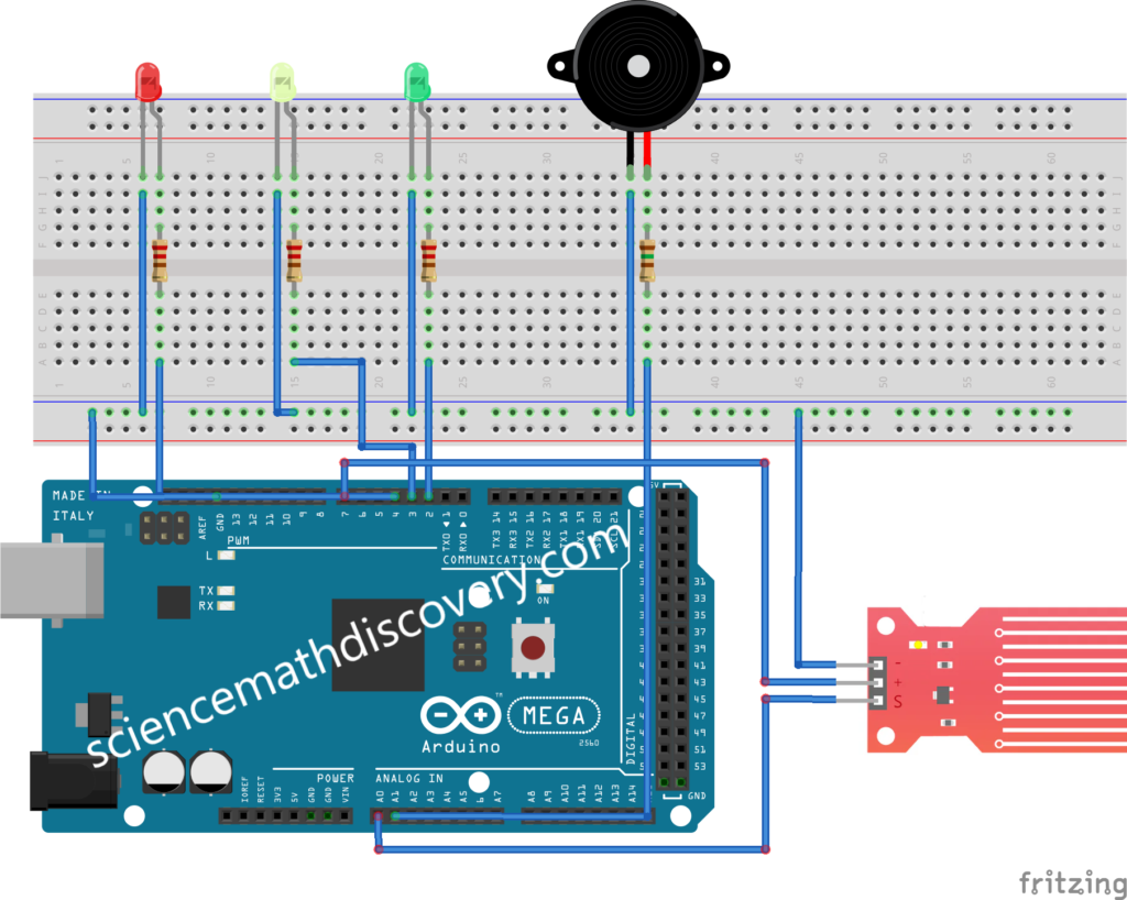
Water Level Indicator using Active Buzzer Tone Piezo Circuit Diagram:
Here’s a simple illustration of the connections:
Steps:
- Connect the HW-038 Water Level Sensor:
- Connect the VCC pin of the HW-038 to the 5V pin on the Arduino.
- Connect the GND pin of the HW-038 to the GND pin on the Arduino.
- Connect the AO (Analog Output) pin of the HW-038 to an analog input pin on the Arduino (e.g., A0).
- Connect the Active Piezo Buzzer:
- Connect the positive terminal of the buzzer to a digital pin on the Arduino (e.g., A1).
- Connect the negative terminal of the buzzer to the GND pin on the Arduino.
Water Level Indicator using Active Buzzer Tone Piezo Code:
Here’s a simple Arduino sketch to read the water level from the HW-038 sensor and trigger the buzzer when the water reaches a certain level.
/* Change these values based on your calibration values */
int lowerThreshold = 400;
int upperThreshold = 500;

// Sensor pins
#define sensorPower 7
#define sensorPin A0
#define buzzerPin A1


// Declare pins to which LEDs are connected
int redLED = 4;
int yellowLED = 3;
int greenLED = 2;

// Value for storing water level
int val = 0;

void setup() {
  pinMode(sensorPin, INPUT);
  pinMode(buzzerPin, OUTPUT);
  Serial.begin(9600); // Initialize serial communication for debugging

    // Set LED pins as an OUTPUT
  pinMode(redLED, OUTPUT);
  pinMode(yellowLED, OUTPUT);
  pinMode(greenLED, OUTPUT);

    // Initially turn off all LEDs
  digitalWrite(redLED, LOW);
  digitalWrite(yellowLED, LOW);
  digitalWrite(greenLED, LOW);
}

void loop() {

int level = readSensor();

if (level == 0) {
    Serial.println("Water Level: Empty");
    digitalWrite(redLED, HIGH);
    digitalWrite(yellowLED, LOW);
    digitalWrite(greenLED, LOW);
    digitalWrite(buzzerPin, HIGH); // Turn on the buzzer
    delay (1000);
    digitalWrite(buzzerPin, LOW);
    delay (1000);
  }
  else if (level > 0 && level <= lowerThreshold) {
    Serial.println("Water Level: Low");
    digitalWrite(redLED, LOW);
    digitalWrite(yellowLED, HIGH);
    digitalWrite(greenLED, LOW);
  }
  else if (level > upperThreshold) {
    Serial.println("Water Level: High");
    digitalWrite(redLED, LOW);
    digitalWrite(yellowLED, LOW);
    digitalWrite(greenLED, HIGH);
    digitalWrite(buzzerPin, LOW); // Turn off the buzzer
    delay(1000);
  }
}
//This is a function used to get the reading
int readSensor() {
  digitalWrite(sensorPower, HIGH);
  delay(10);
  val = analogRead(sensorPin);
  digitalWrite(sensorPower, LOW);
  return val;
}
Explanation:
- The
sensorPinis connected to the analog output of the HW-038 sensor, which gives a variable voltage depending on the water level. - The
buzzerPinis connected to the active piezo buzzer, which sounds when the water level exceeds the defined threshold value. - The
thresholdValueis an analog value (0-1023) corresponding to the water level that triggers the buzzer. Adjust this value based on your specific needs and the calibration of the HW-038 sensor.
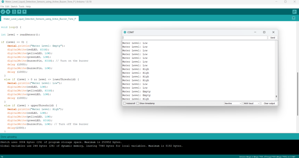
Calibration and Testing:
- Upload the Arduino sketch to your board.
- Open the Serial Monitor (Ctrl+Shift+M) to see the analog values from the HW-038 sensor.
- Submerge the sensor to different levels to see how the analog value changes.
- Adjust the
thresholdValuein the code until the buzzer triggers at the desired water level.
This project provides a straightforward way to monitor water levels and alert you with a buzzer when the water reaches a specific level. The Arduino makes it easy to adjust and expand the functionality as needed. This simple water level indicator can be expanded with additional sensors or connected to a microcontroller for more complex monitoring and control systems.
Expertise on Engineering.
Robotic and microcontroller are like toys to me.
I love playing with them.