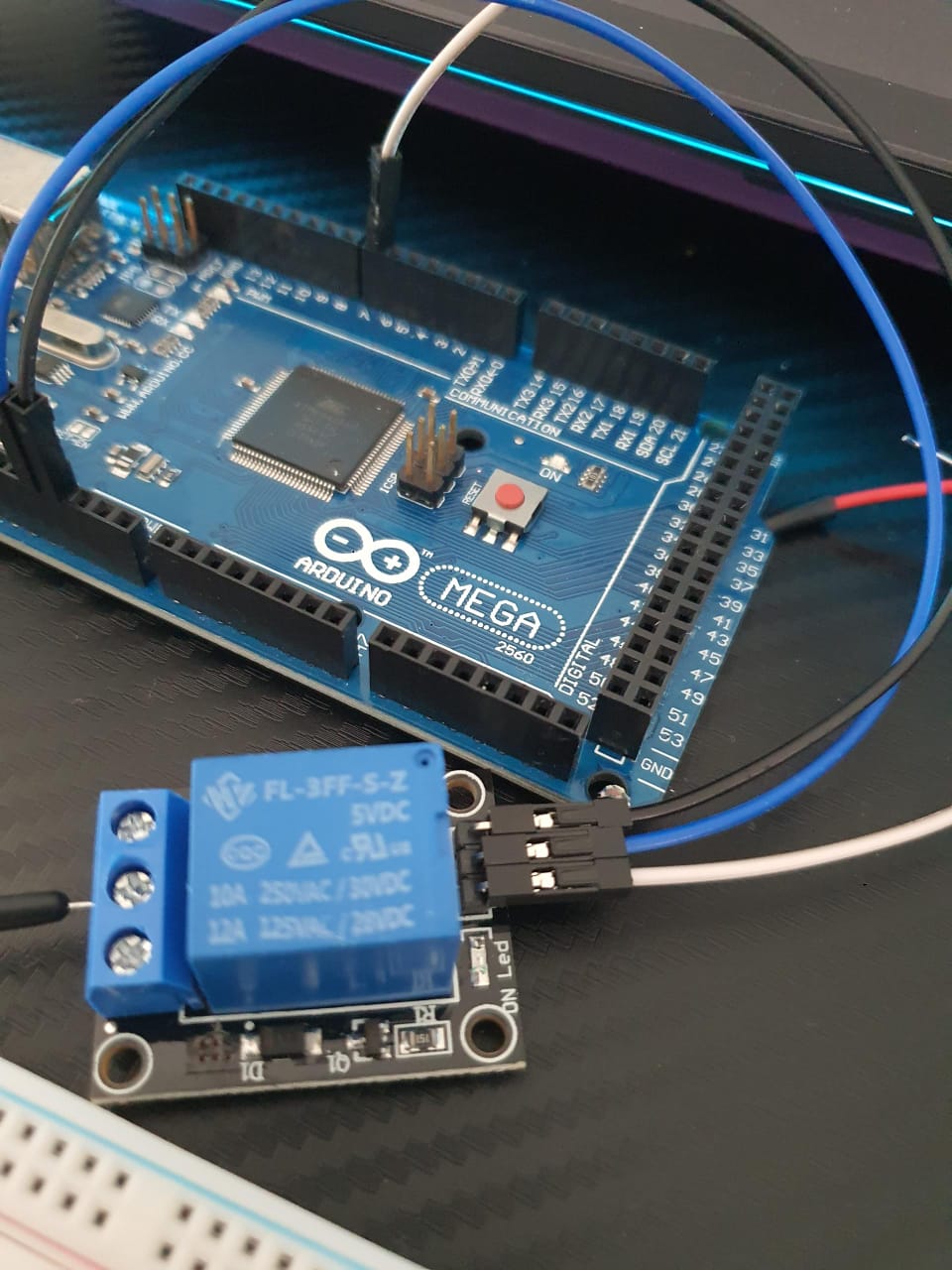
The KY-019 5V Relay Module is an electromechanical switch that allows a low-power control circuit to switch a high-power load on or off. Here’s a detailed explanation of how does the KY-019 5V Relay Module works:
Components of the KY-019 5V Relay Module
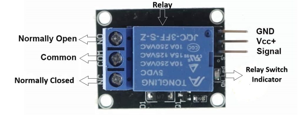
- Relay: The main component, an electromechanical switch.
- Control Pin (IN): The input pin that receives the control signal (usually from a microcontroller like an Arduino).
- VCC: The power supply pin for the relay’s coil, typically 5V.
- GND: The ground connection.
- COM (Common): The common terminal for the relay’s switch.
- NO (Normally Open): The terminal that is disconnected from COM when the relay is not energized.
- NC (Normally Closed): The terminal that is connected to COM when the relay is not energized.
Working Principle
- Power Supply: The relay module is powered by connecting the VCC pin to a 5V power source and the GND pin to ground.
- Control Signal: The IN pin is connected to a digital output pin of a microcontroller (like an Arduino). When this pin is set HIGH (typically 5V), it activates the relay’s coil.
- Electromagnetic Activation: When the control signal is HIGH, current flows through the coil inside the relay, generating a magnetic field. This magnetic field pulls a switch within the relay, changing its state.
- Switching: When the relay is not energized (control signal LOW), the COM terminal is connected to the NC terminal. When the relay is energized (control signal HIGH), the COM terminal switches to connect to the NO terminal.
- Controlling High-Power Loads: By connecting a high-power load circuit to the COM and NO terminals (or COM and NC, depending on the desired default state), the relay can control the connection of this load. The microcontroller can thus turn the high-power load on or off by simply sending a low-power signal to the relay.
Example Use Case
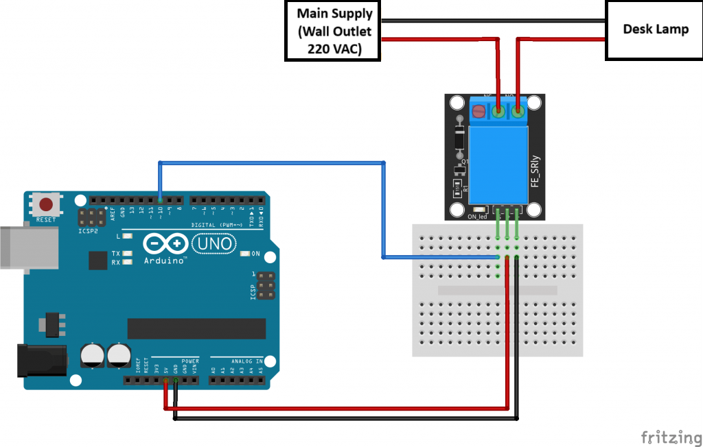
Suppose you want to control a lamp connected to the mains power using an Arduino:
- Connect the Lamp:
- Wire the COM terminal of the relay to one side of the lamp.
- Connect the other side of the lamp to the live wire of the mains supply.
- Connect the NO terminal of the relay to the neutral wire of the mains supply.
- Connect the Relay to Arduino:
- Connect the VCC and GND pins of the relay to the 5V and GND pins of the Arduino.
- Connect the IN pin of the relay to a digital pin (e.g., 10) of the Arduino.
- Arduino Code:
   int relayPin = 10; // Pin connected to IN pin of relay

   void setup() {
     pinMode(relayPin, OUTPUT); // Set the relay pin as output
     digitalWrite(relayPin, LOW); // Initially turn the relay off
   }

   void loop() {
     digitalWrite(relayPin, HIGH); // Turn the relay on
     delay(1000); // Wait for a second
     digitalWrite(relayPin, LOW); // Turn the relay off
     delay(1000); // Wait for a second
   }
In this example, the lamp will turn on for one second and then off for one second repeatedly.
Safety Note
When working with high voltages, ensure that you follow proper safety protocols to avoid electric shocks or damage to your components. Always isolate the low-voltage control side from the high-voltage load side properly.
Expertise on Engineering.
Robotic and microcontroller are like toys to me.
I love playing with them.