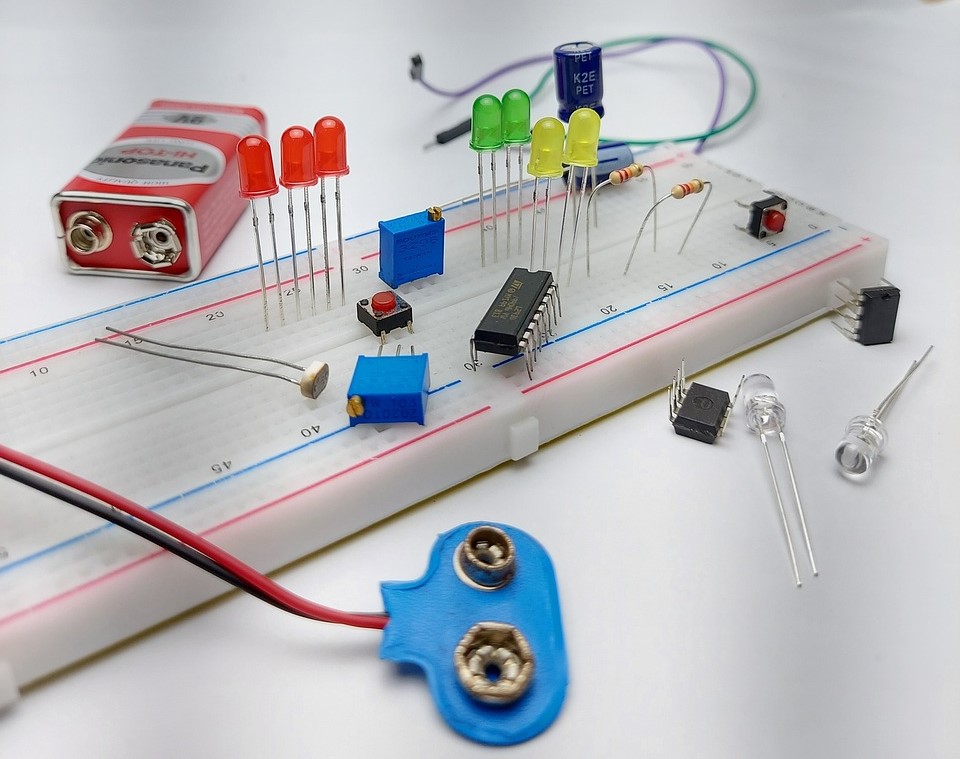
A breadboard serves as a fundamental instrument in electronics prototyping. It’s a reusable tool enabling the creation and testing of electronic circuits without soldering. Frequently employed by hobbyists, students, and engineers, breadboards facilitate the swift assembly of circuits and modifications without the permanent nature of soldered connections. Let’s delve into the basics of breadboarding and how connections are established on it.
Breadboard Basics
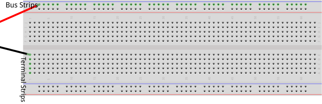
- Contact Points: Breadboards have a grid of small holes or slots that act as contact points. These contact points are usually arranged in a rectangular pattern, with each row and column electrically connected.
- Terminal Strips: The breadboard typically has two sets of vertical strips on the sides, called terminal strips or power rails. These strips are used for supplying power to the circuit components. The top strip is usually connected to the positive voltage source (+5V or +3.3V), and the bottom strip is connected to the ground (GND).
- Bus Strips: Breadboards often have horizontal strips, known as bus strips, that run perpendicular to the terminal strips. These bus strips are used for distributing power or creating common connections between components.
- Breadboard Pins: Some breadboards have metal or plastic pins on the bottom, allowing them to be inserted into a breadboard socket or connected to other breadboards for larger projects.
Breadboard Connections
To utilize a breadboard, you typically insert electronic components such as resistors, capacitors, integrated circuits (ICs), and jumper wires into the contact points to form a circuit. Connections between components are established by positioning them so that their leads or legs make electrical contact with the metal strips beneath the breadboard’s surface.
Jumper wires play a key role in bridging connections between different components on the breadboard. These wires, available in solid-core or flexible variants, feature male connectors at both ends. To establish a connection, insert one end of the jumper wire into the contact point of one component and the other end into the contact point of another component.
The gap in the middle of the breadboard allows for segmentation of connections. Components positioned across the gap remain electrically isolated unless the gap is bridged with jumper wires. This segmentation feature proves useful when you need to isolate specific sections of your circuit.
Using a breadboard enables experimentation with various circuit designs, component testing, and rapid iteration without soldering. Once satisfied with your prototype, you can transition the circuit to a more permanent solution such as a printed circuit board (PCB) or solder the components together for a finalized version.
Breadboard Prototyping Tips
- Plan your circuit layout before placing components on the breadboard to ensure efficient use of space.
- Use the power rails to provide voltage and ground connections to multiple components.
- Keep your circuit neat and organized by using short jumper wires and arranging components logically.
- Use colored jumper wires or labels to differentiate between different signals or sections of your circuit.
Breadboards play a crucial role in electronics prototyping, valued for their simplicity, versatility, and user-friendliness. They enable rapid and convenient circuit assembly and find widespread application in educational environments, electronics laboratories, and do-it-yourself (DIY) projects. In our upcoming project, we’ll delvelop into breadboard prototyping, particularly involving Arduino.
Expertise on Engineering.
Robotic and microcontroller are like toys to me.
I love playing with them.