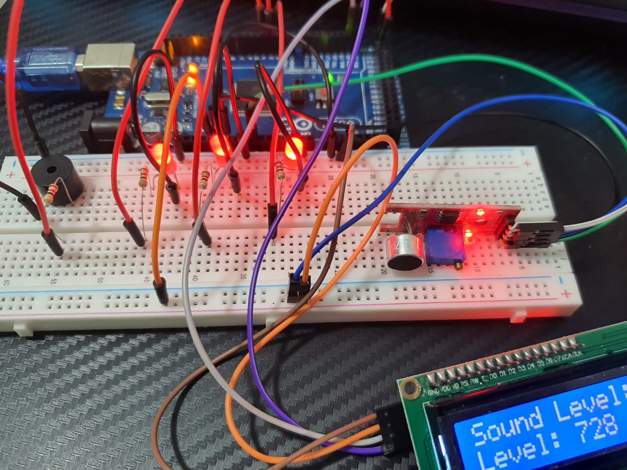
Microphone Sound Sensor using LCD Display and Active Buzzer: Here’s a more comprehensive setup that includes the KY-037 Microphone Sound Sensor, a 16×2 LCD display, an active buzzer, and multiple LEDs. This setup will allow you to display sound levels on the LCD, indicate sound detection with LEDs, and sound an active buzzer when a certain sound level is detected.
Components Needed:
- Arduino Mega Board
- KY-037 Microphone Sound Sensor
- 16×2 LCD Display with I2C Interface
- Active Buzzer Tone Piezo
- LEDs (e.g., 3 LEDs for different sound levels)
- Resistors (220Ω for each LED)
- Resistor 150Ω
- Breadboard and jumper wires
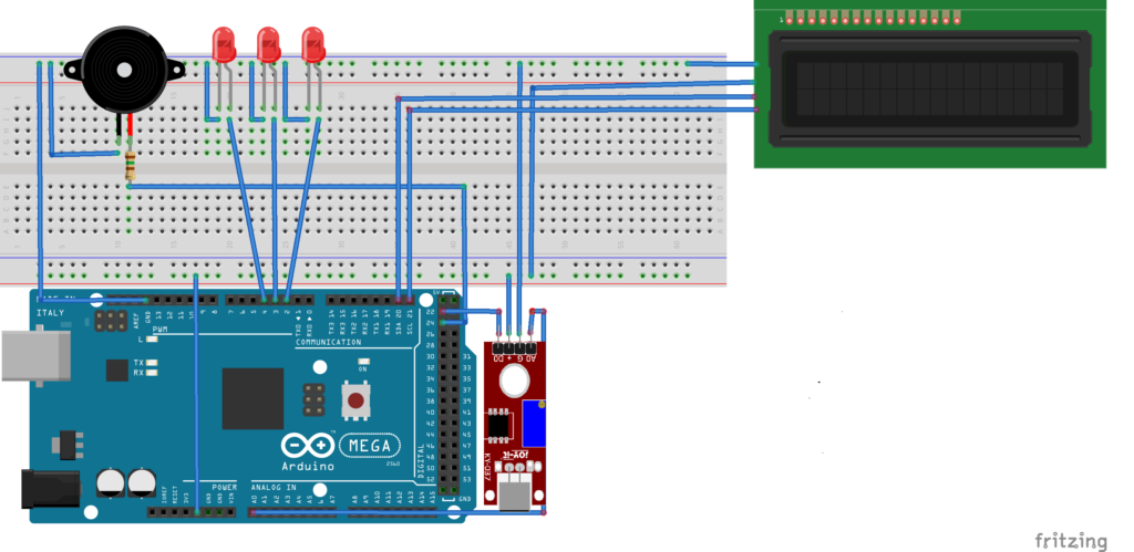
Circuit Connections:
KY-037 Microphone Sound Sensor:
- VCC: Connect to 5V on the Arduino
- GND: Connect to GND on the Arduino
- AO (Analog Output): Connect to an analog input pin on the Arduino Mega (e.g., A0)
- DO (Digital Output): Connect to a digital input pin on the Arduino Mega (e.g., 22)
16×2 LCD Display with I2C Interface:
- VCC: Connect to 5V on the Arduino Mega
- GND: Connect to GND on the Arduino Mega
- SDA: Connect to SDA 20 on the Arduino Mega
- SCL: Connect to SCL 21 on the Arduino Mega
Active Buzzer:
- Positive (longer leg): Connect to a digital output pin on the Arduino Mega (e.g., 24)
- Negative (shorter leg): Connect to GND on the Arduino
LEDs:
- Anode (longer leg) of each LED: Connect through a 220Ω resistor to a digital output pin on the Arduino (e.g., 2, 3, 4)
- Cathode (shorter leg) of each LED: Connect to GND on the Arduino
Circuit Diagram:
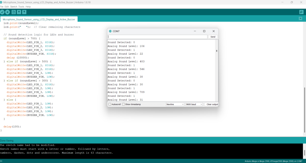
Example Arduino Code:
#include <Wire.h>
#include <LiquidCrystal_I2C.h>

#define SOUND_SENSOR_PIN A0  // Analog pin for sound sensor
#define SOUND_SENSOR_DIGITAL_PIN 22  // Digital pin for sound sensor
#define BUZZER_PIN 24         // Digital pin for active buzzer
#define LED_PIN_1 2           // Digital pin for LED 1
#define LED_PIN_2 3           // Digital pin for LED 2
#define LED_PIN_3 4           // Digital pin for LED 3

LiquidCrystal_I2C lcd(0x27, 16, 2);  // I2C address 0x27 for a 16 chars and 2 line display

void setup() {
  pinMode(SOUND_SENSOR_PIN, INPUT);
  pinMode(SOUND_SENSOR_DIGITAL_PIN, INPUT);
  pinMode(BUZZER_PIN, OUTPUT);
  pinMode(LED_PIN_1, OUTPUT);
  pinMode(LED_PIN_2, OUTPUT);
  pinMode(LED_PIN_3, OUTPUT);

  lcd.init();
  lcd.backlight();
  lcd.setCursor(0, 0);
  lcd.print("Sound Level:");
  Serial.begin(9600);
}

void loop() {
  // Read analog value
  int soundLevel = analogRead(SOUND_SENSOR_PIN);
  Serial.print("Analog Sound Level: ");
  Serial.println(soundLevel);

  // Read digital value
  int soundDetected = digitalRead(SOUND_SENSOR_DIGITAL_PIN);
  Serial.print("Sound Detected: ");
  Serial.println(soundDetected);

  // Update LCD with sound level
  lcd.setCursor(0, 1);
  lcd.print("Level: ");
  lcd.print(soundLevel);
  lcd.print("   ");  // Clear remaining characters

  // Sound detection logic for LEDs and buzzer
  if (soundLevel > 700) {
    digitalWrite(LED_PIN_1, HIGH);
    digitalWrite(LED_PIN_2, HIGH);
    digitalWrite(LED_PIN_3, HIGH);
    digitalWrite(BUZZER_PIN, HIGH);
    delay (10000);
  } else if (soundLevel > 500) {
    digitalWrite(LED_PIN_1, HIGH);
    digitalWrite(LED_PIN_2, HIGH);
    digitalWrite(LED_PIN_3, LOW);
    digitalWrite(BUZZER_PIN, LOW);
  } else if (soundLevel > 300) {
    digitalWrite(LED_PIN_1, HIGH);
    digitalWrite(LED_PIN_2, LOW);
    digitalWrite(LED_PIN_3, LOW);
    digitalWrite(BUZZER_PIN, LOW);
  } else {
    digitalWrite(LED_PIN_1, LOW);
    digitalWrite(LED_PIN_2, LOW);
    digitalWrite(LED_PIN_3, LOW);
    digitalWrite(BUZZER_PIN, LOW);
  }

  delay(100);
}
Explanation of the Code:
- Libraries: Includes the
Wirelibrary for I2C communication and theLiquidCrystal_I2Clibrary for the LCD display. - Pin Definitions: Defines pins for the sound sensor, LEDs, and buzzer.
- Setup Function:
- Initializes the pins.
- Sets up the LCD display and prints the initial message.
- Starts serial communication for debugging.
4. Loop Function:
- Reads the analog value from the sound sensor.
- Reads the digital value from the sound sensor.
- Updates the LCD display with the current sound level.
- Controls the LEDs and buzzer based on the sound level.
This setup provides a comprehensive system for detecting and displaying sound levels, and it visually and audibly alerts based on the sound intensity detected by the KY-037 sensor. Adjust the thresholds in the code as needed for your specific application.
Expertise on Engineering.
Robotic and microcontroller are like toys to me.
I love playing with them.